Introduction
A while ago I ordered a STM32 Blue Pill board. This normally features a STM32F103C8T6 microcontroller, however, mine has a STM32F103C6T6 on it. I decided to program it using libopencm3 (http://libopencm3.org/). As the STMF103C6T6 does not feature a floating point unit (FPU), I thought I’d play with fixed point numbers a little. In this post, I will document the simple fixed-point arithmetic I implemented and show how to use
- Timers and Timer Interrupts
- I2C
- USART
- GPIOs
with libopencm3.
As the setup process for libopencm3 and a template project are provided, I will not cover this here.
Resources
- template project for libopencm3 https://github.com/libopencm3/libopencm3-template
- examples for libopencm3 https://github.com/libopencm3/libopencm3-examples
- libopencm3 doxygen documentation http://libopencm3.org/docs/latest/stm32f1/html/modules.html
- stm32f103c6t6 reference manual (google)
- tmp102 datasheet (google)
Fixed-Point Numbers
A floating point number is pretty much a number where the decimal point can move about as needed. The standard IEEE754 documents floats and shows how they work. Typically, without having a FPU, the calculations underlying floating points are expensive. Thus, in application where no floating point numbers are available, for instance in microcontrollers without an FPU or in a FGPA, fixed-point numbers come into play.
A fixed-point number is a scaled integer value with a decimal point that does not move, hence the fixed. As an example, I’ll use an 8-Bit signed integer. To denote where the decimal point is, you can use the Q-Format. Thus, Q3.4 means the decimal point is in the “middle”, the MSB is used to store the sign value.
That means if you have Q3.4, you need $m + n + 1$ bits to represent it. There are 3 bits for the decimal part and 4 bits for the fractional part:
Q3.4
    sign |   2^2 2^1 2^0   |  2^-1 2^-2 2^-3 2^-4
bit 7    |   6   5   4     |  3    2    1    0
    0    |   0   0   0     |  0    0    0    0
For fixed-point numbers with a sign bit, we have the range $−2^m to +2^m − 2^{−n }$, in the case of the Q3.4 that is:
$$ [-2^3 ; +2^3 - 2^{-4}] = [ -8 ; 7.9375 ] $$
Note that we’re still working with integer values under the hood, we just “imagine” the decimal point and scale the integer.
Let’s expand this to 16-bit signed integers and work with those Q11.4 = 11 + 4 + 1 = 16 bits
To define this in code, let’s first set our fractional bits:
#define FRAC_BITS_16 4
… and define a type to distinguish fixed points from integers:
typedef int16_t fp16;
Float to Fixed and Vice Versa
To convert from float to fixed, we use:
#define FLOAT2FIXED16(n) ( (fp16)(n * (1 << FRAC_BITS_16)) )
To convert from fixed to float, we use:
#define FIXED2FLOAT16(n) ( ((float)n / (1 << FRAC_BITS_16)) )
Note that both operations are just scaling, nothing more.
Basic Arithmetic
For the arithmetic functions, I will define inline functions.
Addition and Subtraction don’t need any special operations.
static inline fp16
fp16_add(int16_t a, int16_t b)
{
    return a + b;
}

static inline fp16
fp16_sub(int16_t a, int16_t b)
{
    return a - b;
}
Multiplication on the other hand requires a scaling operation to take place:
static inline fp16
fp16_mul(int16_t a, int16_t b)
{
    return (fp16)((((int32_t)a) * ((int32_t)b)) >> FRAC_BITS_16);
}
The important thing about this operation is that the integers we multiply are cast to double their width. So, for 16-bit integers, we need to cast to 32-bit integers. The multiplication is done on 32-bit integers, the result is again scaled and cast back to a fixed point (just a int16_t).
An example:
Take two Q3.4 numbers and multiply them.
q0 = 2.5
q1 = 2.0

# | separates off the sign bit
# . shows where the decimal point "would be"
q0 = 0|010.1000 = 00101000 = 40
q1 = 0|010.0000 = 00010000 = 32

# without the decimal point, we calculate 40*48
q2 = q0 * q1 = 40 * 32 = 1280 = 0x500 = 0101|0000|0000

# we are above 16 bits at this point, that's why we cast for the multiplication
# the result is also wrong at the moment, we need to scale back in order to get the correct result
0101|0000|0000 >> 4 = 0101|0000 = 5
For Division we get:
/**
 * divide two numbers
 */
static inline fp16
fp16_div(int16_t a, int16_t b)
{
    return (fp16)( ( ((int32_t)a) << FRAC_BITS_16 ) / b);
}
The dividend is scaled by the fractional bits, then divided by the divisor. In the end, we have to cast again.
Example:
With Q3.4 numbers again
q0 = 0010|0000 = 32
q1 = 0010|0000 = 32

# scale
00100000 << 4 = 001000000000 = 512
# divide
001000000000 / 00100000 = 512 / 32 = 16
# result
16 = 0001|0000 = 1.0
As the divisor is still scaled, we need to take this into account in the dividend, thus the shift by the fractional bits.
The Mini-Project
The goal of the project is to take a measurement from the TMP102 temperature sensor by Texas Instruments every x seconds. This means we need a timer interrupt every x seconds and a working I2C communication. The data that is measured is filtered via a simple moving average filter, thus the fixed-point numbers and sent via the UART to my laptop.
It may be overkill to filter here, as the TMP102 is not very noisy, but I wanted to do more than just take a simple measurement.
Clock Setup
In the standard configuration, the STM32F103C6T6 peripheral clock runs at 8Mhz. That’s good enough. So from here, we just have to activate the peripheral clocks:
static void
clock_setup(void)
{
    rcc_periph_clock_enable(RCC_GPIOA);
    rcc_periph_clock_enable(RCC_GPIOB);
    rcc_periph_clock_enable(RCC_GPIOC);
    rcc_periph_clock_enable(RCC_AFIO);
    rcc_periph_clock_enable(RCC_I2C1);
    rcc_periph_clock_enable(RCC_USART1);
    rcc_periph_clock_enable(RCC_TIM2);
}
Note that we need AFIO (Alternate Function) to configure the alternate function modes of the GPIO pins used for USART and I2C. Also, I will utilize the onboard LED of the Blue Pill, connected to PC13.
I2C
In this simple case, I2C setup is straight-forward (http://libopencm3.org/docs/latest/stm32f1/html/group__i2c__file.html#ga5e8fee505dc3d5c99e2385e2074ff3df):
static void i2c_setup(void)
{

    /* Set alternate functions for the SCL and SDA pins of I2C1. */
    gpio_set_mode(GPIOB, GPIO_MODE_OUTPUT_50_MHZ,
              GPIO_CNF_OUTPUT_ALTFN_OPENDRAIN,
              GPIO_I2C1_SCL | GPIO_I2C1_SDA);

    /* Disable the I2C before changing any configuration. */
    i2c_peripheral_disable(I2C1);

    /* APB1 is running at 8MHz. */
    i2c_set_clock_frequency(I2C1, 8);

    /* speed setting according to TMP102 */
    i2c_set_speed(I2C1, i2c_speed_sm_100k, 8);

    /* 100KHz */
    i2c_set_standard_mode(I2C1);

    /* If everything is configured -> enable the peripheral. */
    i2c_peripheral_enable(I2C1);
}
USART
Again, really straight-forward, we’re just configuring this to a speed of 9600 Baud with 8N1 configuration. Note that we only need USART TX, we don’t receive.
static void
usart_setup(void)
{
    /* Setup GPIO pin GPIO_USART1_RE_TX on GPIO port B for transmit. */
    gpio_set_mode(GPIOA, GPIO_MODE_OUTPUT_50_MHZ,
              GPIO_CNF_OUTPUT_ALTFN_PUSHPULL, GPIO_USART1_TX);

    /* Setup UART parameters. */
    usart_set_baudrate(USART1, 9600);
    usart_set_databits(USART1, 8);
    usart_set_stopbits(USART1, USART_STOPBITS_1);
    usart_set_parity(USART1, USART_PARITY_NONE);
    usart_set_flow_control(USART1, USART_FLOWCONTROL_NONE);
    usart_set_mode(USART1, USART_MODE_TX);

    /* Finally enable the USART. */
    usart_enable(USART1);
}
Timer
Next, the timer setup. This features and interrupt and is a little bit more involved:
static void
timer_setup(void)
{
    /* this timer setup is taken 1:1 from the
       timer example of this repository */

    nvic_enable_irq(NVIC_TIM2_IRQ);
    rcc_periph_reset_pulse(RST_TIM2);

    timer_set_mode(TIM2, TIM_CR1_CKD_CK_INT,
        TIM_CR1_CMS_EDGE, TIM_CR1_DIR_UP);

    timer_set_prescaler(TIM2, (8000-1));

    timer_disable_preload(TIM2);
    timer_continuous_mode(TIM2);

    /* with the input frequency being 1000kHz, we can use this
       value to control the timer interrupts in seconds.
       1000 = 1     sec
        500 = 0.5   sec
        250 = 0.25  sec
        125 = 0.125 sec
        20  = 0.02  sec == 50 Hz
    */

    timer_set_period(TIM2, 250);

    timer_enable_counter(TIM2);
    timer_enable_irq(TIM2, TIM_DIER_CC1IE);
}
The input clock for the timer runs at 8Mhz, I divide that down by 8000 using the timer_set_prescaler function. This reduces the clock speed for the timer to 1kHz. After that, the timer frequency can be controlled by timer_set_period. I set this to 250, thus the timer triggers and interrupt every 0.25 seconds.
For the IRQ, don’t forget to enable it in the NVIC and in the peripheral.
Onboard LED
All we do here is set a push-pull configuration in slow mode.
static void
gpio_setup(void)
{
    gpio_set_mode(GPIOC,
        GPIO_MODE_OUTPUT_2_MHZ,
        GPIO_CNF_OUTPUT_PUSHPULL,
        GPIO13
    );
}
Interrupt Service Routine
This is the ISR. Once a timer interrupt is triggered, we read the sensor. The data is delivered in the following format:
# 12-bits of data
byte 0 = MSB  0000 0000
byte 1 = LSB  0000 xxxx

# byte 0 contains the most significant 8 bits
# byte 1 contains the 4 least significant bits
# xxxx marks irrelevant parts
I am using Q11.4 numbers, this corresponds exactly what the sensor outputs:
# s = sign-bit
# d = decimal part
# f = fractional part
byte 0    | byte 1
0000 0000 . 0000
sddd dddd . ffff
With a little bit of bitshifting, we can convert this to Q11.4:
fp16 temp = ( ((uint16_t)buffer[0] << 4) | ((uint16_t)buffer[1] >> 4) );
This cuts off the irrelevant parts of the LSB and puts the MSB part into the correct position.
Here is how you read the sensor:
static void
read_sensor(uint8_t *p_buf)
{
    uint8_t temp_reg = PRB_TEMPERATURE;

    i2c_transfer7(I2C1, TMP102_DEVICE_ADDR, &temp_reg, 1,
        &p_buf[0], TEMPERATURE_READ_BYTES);

}
The i2c_transfer7 function takes the device address, the register we ant to read (+ the datasize) and a buffer to store the result (+ buffer size). That’s it. Note that this function generates a repeated start condition, which we need to read the TMP102. Thus, with a setup function for I2C and one line of code, we can read the TMP102 temperature register, neat.
… and this is the full code for the ISR:
void
tim2_isr(void)
{
    /* buffer to store the raw sensor values and filtered values
       buffer[0], buffer[1] = raw sensor values
       buffer[2], buffer[3] = fp16 with 4 fracbits split into MSB | LSB
     */

    uint8_t buffer[4] = { 0x00 };

    if(timer_get_flag(TIM2, TIM_SR_CC1IF))
    {
        /* clear the interrupt */
        timer_clear_flag(TIM2, TIM_SR_CC1IF);

        /* read from the sensor */
        read_sensor(&buffer[0]);

        /* filter data */

        /* to fixed point */
        fp16 temp = ( ((uint16_t)buffer[0] << 4) | ((uint16_t)buffer[1] >> 4) );
        /* add to buffer */
        circ_buf_put(&g_cbuf, temp);
        /* convolution */
        fp16 filt = circ_buf_convolution(&g_cbuf, &g_fcoeff[0]);
        /* to raw bytes */
        buffer[2] = (uint8_t)( (filt >> 8) & 0xff);
        buffer[3] = (uint8_t)( filt & 0xff);

        /* send what we read via UART */
        send_data(&buffer[0]);

        /* toggle the LED to see if we're still alive or not */
        gpio_toggle(GPIOC, GPIO13);
    } /* if */
}
Now for the last two parts.
- Filtering the Data
All of the data is placed into a circular buffer with a width of i fp16 numbers. That means the buffer stores the last i samples from the sensor at all times.
Via convolution with an array, also consisting of i fp16 values, the filtered result is obtained. For a moving average filter this is just an array of i times 1/i. This is pre-calculated.
array[i] = { 1/i, 1/i ... 1/i }
- Send the data out via the UART (
send_data)
static void
send_data(uint8_t *buf)
{
    usart_send_blocking(USART1, buf[0]);
    usart_send_blocking(USART1, buf[1]);
    usart_send_blocking(USART1, buf[2]);
    usart_send_blocking(USART1, buf[3]);

    usart_send_blocking(USART1, '\r');
    usart_send_blocking(USART1, '\n');
}
Here, bytes 0 and 1 contain the raw value and bytes 2 and 3 contain the filtered value.
Full Code
Here is everything, I just packed the fixed point stuff into a separate header file.
/**
 * @brief example of using I2C with the STM32F103C6T6A and
 *        a TMP102 by TI
 *
 * @description
 *  this project reads the temperature from a TMP102 sensor.
 *  if you see @man in here, consult the datasheet of the TMP102
 *
 * @author 0xca7
 */

#include <libopencm3/cm3/nvic.h>

#include <libopencm3/stm32/rcc.h>
#include <libopencm3/stm32/gpio.h>
#include <libopencm3/stm32/i2c.h>
#include <libopencm3/stm32/usart.h>
#include <libopencm3/stm32/timer.h>

#include <fixed16.h>

/** @brief the device address of the TMP102 sensor */
#define TMP102_DEVICE_ADDR      0x48

/** @brief pointer register byte */
#define PRB_TEMPERATURE         0x00
#define PRB_CONFIGURATION       0x01
#define PRB_TLOW                0x02
#define PRB_THIGH               0x03

/** @brief the number of bytes we need for temperature measurement */
#define TEMPERATURE_READ_BYTES  0x02

/** @brief a circular buffer used for filtering */
#define CIRC_BUFFER_SIZE    4
typedef struct
{
    volatile uint16_t q[CIRC_BUFFER_SIZE];
    volatile uint8_t head;
}
circ_buf_t;

/** @brief filter coefficients */
static fp16 g_fcoeff[CIRC_BUFFER_SIZE] = { 0x00 };

/** @brief circ buffer used for filtering */
static circ_buf_t g_cbuf = { 0x00 };

/** @brief initialize the buffer to a reset state */
static void
circ_buf_init(circ_buf_t *p_buf)
{
    int i = 0;
    for(i = 0; i < CIRC_BUFFER_SIZE; i++)
    {
        p_buf->q[i] = 0;
    }
    p_buf->head = 0;
}

fp16
circ_buf_convolution(circ_buf_t *p_buf, fp16 *h)
{
    int i = 0;
    int cursor = p_buf->head;

    fp16 res = FLOAT2FIXED16(0.0);

    for(i = 0; i < CIRC_BUFFER_SIZE; i++)
    {
        cursor--;
        if(cursor < 0)
        {
            cursor = CIRC_BUFFER_SIZE-1;
        }
        res = fp16_add(res,
            fp16_mul(p_buf->q[cursor], *(h+i)));
    }

    return res;
}

void
circ_buf_put(circ_buf_t *p_buf, uint16_t val)
{
    p_buf->q[p_buf->head] = val;

    /* less expensive than modulo */
    if(++(p_buf->head) == CIRC_BUFFER_SIZE)
    {
        p_buf->head = 0;
    }
}

/**
 * @brief   performs clock setup for all needed peripherals
 * @note    this MUST be the first function called before all
 *          all other setup functions
 * @param   void
 * @return  void
 */
static void
clock_setup(void)
{
	rcc_periph_clock_enable(RCC_GPIOA);
	rcc_periph_clock_enable(RCC_GPIOB);
	rcc_periph_clock_enable(RCC_GPIOC);
	rcc_periph_clock_enable(RCC_AFIO);
	rcc_periph_clock_enable(RCC_I2C1);
	rcc_periph_clock_enable(RCC_USART1);
	rcc_periph_clock_enable(RCC_TIM2);
}

/**
 * @brief   sets up I2C with 100kHz in standard mode
 * @note    requires GPIOB and I2C1 clocks to be enabled
 * @param   void
 * @return  void
 */
static void i2c_setup(void)
{

	/* Set alternate functions for the SCL and SDA pins of I2C1. */
	gpio_set_mode(GPIOB, GPIO_MODE_OUTPUT_50_MHZ,
		      GPIO_CNF_OUTPUT_ALTFN_OPENDRAIN,
		      GPIO_I2C1_SCL | GPIO_I2C1_SDA);

	/* Disable the I2C before changing any configuration. */
	i2c_peripheral_disable(I2C1);

	/* APB1 is running at 36MHz. */
	i2c_set_clock_frequency(I2C1, 8);

    /* this may not be needed */
    i2c_set_speed(I2C1, i2c_speed_sm_100k, 8);

	/* 100KHz */
	i2c_set_standard_mode(I2C1);

	/* If everything is configured -> enable the peripheral. */
	i2c_peripheral_enable(I2C1);
}

/**
 * @brief   sets up the USART with 8N1 - TX only with 9600 Baud
 * @note    requires GPIOA and USART1 clocks to be enabled
 * @param   void
 * @return  void
 */
static void
usart_setup(void)
{
    /* Setup GPIO pin GPIO_USART1_RE_TX on GPIO port B for transmit. */
    gpio_set_mode(GPIOA, GPIO_MODE_OUTPUT_50_MHZ,
              GPIO_CNF_OUTPUT_ALTFN_PUSHPULL, GPIO_USART1_TX);

    /* Setup UART parameters. */
    usart_set_baudrate(USART1, 9600);
    usart_set_databits(USART1, 8);
    usart_set_stopbits(USART1, USART_STOPBITS_1);
    usart_set_parity(USART1, USART_PARITY_NONE);
    usart_set_flow_control(USART1, USART_FLOWCONTROL_NONE);
    usart_set_mode(USART1, USART_MODE_TX);

    /* Finally enable the USART. */
    usart_enable(USART1);
}

static void
timer_setup(void)
{
    /* this timer setup is taken 1:1 from the
       timer example of this repository */

    nvic_enable_irq(NVIC_TIM2_IRQ);
    rcc_periph_reset_pulse(RST_TIM2);

    timer_set_mode(TIM2, TIM_CR1_CKD_CK_INT,
        TIM_CR1_CMS_EDGE, TIM_CR1_DIR_UP);

    timer_set_prescaler(TIM2, (8000-1));

	timer_disable_preload(TIM2);
	timer_continuous_mode(TIM2);

    /* with the input frequency being 1000kHz, we can use this
       value to control the timer interrupts in seconds.
       1000 = 1     sec
        500 = 0.5   sec
        250 = 0.25  sec
        125 = 0.125 sec
        20  = 0.02  sec == 50 Hz
    */

    timer_set_period(TIM2, 250);

    timer_enable_counter(TIM2);
    timer_enable_irq(TIM2, TIM_DIER_CC1IE);
}

/**
 * @brief configure the onboard LED as an output
 * @param void
 * @return void
 */
static void
gpio_setup(void)
{
    gpio_set_mode(GPIOC,
        GPIO_MODE_OUTPUT_2_MHZ,
        GPIO_CNF_OUTPUT_PUSHPULL,
        GPIO13
    );
}

/**
 * @brief this function reads from the sensor
 * @warning the buffer needs to be 3 bytes in size
 * @param p_buf the buffer to read to
 * @return void
 */
static void
read_sensor(uint8_t *p_buf)
{
    /*
        1. we have to write the value of the register we want
           to access into the pointer register. For this example,
           we write 0x00, which I called PRB_TEMPERATURE because
           we want to read the temperature register @man.
        2. after that, we send start and read two bytes.
    */
    uint8_t temp_reg = PRB_TEMPERATURE;

    i2c_transfer7(I2C1, TMP102_DEVICE_ADDR, &temp_reg, 1,
        &p_buf[0], TEMPERATURE_READ_BYTES);

}

/**
 * @brief this function sends the sensor data via the UART
 * @param p_buf the buffer to send
 * @return void
 */
static void
send_data(uint8_t *buf)
{
    /*
        the temperature reading returns three bytes,
        the MSB, LSB and a PEC (CRC-8 checksum), we only
        care about the reading to keep things simple so we
        only send the raw MSB and LSB.
    */
    usart_send_blocking(USART1, buf[0]);
    usart_send_blocking(USART1, buf[1]);
    usart_send_blocking(USART1, buf[2]);
    usart_send_blocking(USART1, buf[3]);

    usart_send_blocking(USART1, '\r');
    usart_send_blocking(USART1, '\n');
}

void
tim2_isr(void)
{
    /* buffer to store the raw sensor values and filtered values
       buffer[0], buffer[1] = raw sensor values
       buffer[2], buffer[3] = fp16 with 4 fracbits split into MSB | LSB
     */

    uint8_t buffer[4] = { 0x00 };

    if(timer_get_flag(TIM2, TIM_SR_CC1IF))
    {
        /* clear the interrupt */
        timer_clear_flag(TIM2, TIM_SR_CC1IF);

        /* read from the sensor */
        read_sensor(&buffer[0]);

        /* filter data */

        /* to fixed point */
        fp16 temp = ( ((uint16_t)buffer[0] << 4) | ((uint16_t)buffer[1] >> 4) );
        /* add to buffer */
        circ_buf_put(&g_cbuf, temp);
        /* convolution */
        fp16 filt = circ_buf_convolution(&g_cbuf, &g_fcoeff[0]);
        /* to raw bytes */
        buffer[2] = (uint8_t)( (filt >> 8) & 0xff);
        buffer[3] = (uint8_t)( filt & 0xff);

        /* send what we read via UART */
        send_data(&buffer[0]);

        /* toggle the LED to see if we're still alive or not */
        gpio_toggle(GPIOC, GPIO13);
    } /* if */
}

int
main(void)
{
    int i = 0;

    circ_buf_init((circ_buf_t*)&g_cbuf);

    /* initialize the filter coefficients */
    for(i = 0; i < CIRC_BUFFER_SIZE; i++)
    {
        g_fcoeff[i] = FLOAT2FIXED16(1.0 / (float)CIRC_BUFFER_SIZE);
    }

	clock_setup();
	i2c_setup();
    usart_setup();
    gpio_setup();

    timer_setup();

	while (1) {}

	return 0;
}
Result
After compiling this, I wrote a small python script that does a live-plot of the temperature via matplotlib:
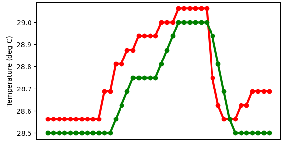
The red line is the raw temperature data, without filtering. The green line shows the temperature data with the moving average filter applied, in this case, it is a 4-point moving average filter (CIRC_BUFFER_SIZE = 4).
Remarks
- the circular buffer does not use modulo as it may be more expensive than the check for overflow by the if-clause
- the global
circ_buf_tis only used in the interrupt. Declaring the members as volatile seems to be a sensible decision - yeah, I could have used a loop in the
send_datafunction - splitting this into multiple files is a good next step
Conclusion
This was a fun little project, libopencm3 is a great library in my opinion. I had a look at the source code, it’s clean and sufficiently commented. The doxygen documentation and the examples the project provides are enough to get something to work. Overall, I can highly recommend this library. This little project should provide you with everything you need to get started and at the same time realizes something halfway decent and useful.